

ignacio_m
-
Content Count
7 -
Joined
-
Last visited
Posts posted by ignacio_m
-
-
I read somewhere that forza doesn't work in god format.. try extracting the ISO if the DVD1 and put it into your games folder..
Ok i'll try and tell you what happens. Thanks very much
-
But if you think it more deeper... Microsoft really needs this stuff for selling more consoles... it's like ps2 on Latinamerica... they know that the most people can't buy many originals...
-
Really thanked... Great tutorial. i'm trying to revive an old jasper that were nand corrupted by the shitty lpt nand dumper...
-
 1
1
-
-
Hello i found some information about the mosfet that i want to share.
How to test and replace Xbox 360 Mosfets
"The Xbox 360 motherboard takes in 12V from the "brick" then converts it down to more useful voltages that the chips can use. Most notably, 5V, 3.3V, and 1.8V. This is done via DC-DC switching converters.
These converters use a pair of MOSFETS (high current transistors) to switch a supply line very rapidly between 12V and ground, to get an "average" voltage of somewhere in between, such as 5V. A controller chip controls the MOSFETS to regulate an exact voltage. The output of these 'FETs then goes through a coil to clean it up, and it's then smoothed up more by some capacitors and such.
Now, these coils have a very small amount of resistance, so a small amount of voltage (very small) is lost across this coil, and the voltage drop is proportional to the amount of current going through the coil. Therefore, by measuring the voltage drop across the coil, the motherboard knows how much current is being used, and it will shut itself off if too much current is being drawn (short circuit protection).
However, the "old" 5V point is straight off the MOSFETS, so current being drawn there does not go through the coil, so the motherboard cannot detect that current being drawn. So, if the point shorts out due to shitty LED wiring or just some stupid mistake, it will draw excessive current, but the motherboard won't know it. So the mobo stays powered up, and frys itself. I have seen three cases of this happening so far.
Symptoms of failure:
-Xbox 360 turns on, and flashes 3 red lights IMMEDIATELY (not after a few seconds like on some other failures, such as the dreaded 0102). No picture on the screen.
-Fans do not spin, and PSU may show red or orange light.
-After it shows the 3 red lights, secondary error code will be 0001 or 0002.
-Nothing connected to 12V or 5V works (no measurable voltage on the line).
-Resistance from 12V to 5V is very low (around 1 ohm)."
You can not test a MOSFET chip while it is in circuit, so it must be desoldered first if you want to test it properly.
- Use at least a 35-55 watt soldering iron with a nice clean tip that has been tinned.
- add some rosin flux where the 3 legs are soldered to the board.
- Then get some desoldering braid/wick and lay a fresh part on top of the solder you want to remove. Heat the solder through the braid, and when it gets hot enough the solder will wick up into the braid. When the braid starts to get saturated with solder, move to a fresh piece of braid and keep wicking until all the solder is removed. Do this for the 3 parts of the MOSFET that are connected to the board. Don't ever use a hand held desoldering pump unless you know it is static safe because most of them which aren't can send out a static shock which could kill a MOSFET.
- Carefully remove the MOSFET, making sure to not damage the pads the legs are soldered to. A dental hook tool, or hemostats should work fine. If you are having a hard time removing the MOSFET, try preheating the area a bit first with a heatgun, or soldering torch from a distance. You could also add some low temp soldering alloy which will help the leaded solder melt at a lower temp.
- An alternative to using a soldering iron is to first add flux and melt on some low melting point solder. Then preheat the board with a heatgun or bottom preheater. Use a hot air rework tool, or heatgun with tiny nozzle to heat it while gently gripping with long tweezers or hemostat tool. The whole MOSFET should come up as the solder melts.
- Now you can test the MOSFET to see if it still works or needs to be replaced. Make sure you don't let any static producing materials get in contact with it (closthes, plastics, etc). You will need a decent multimeter that has a diode test/continuity mode option with a rating of at least 3.3 volt over d.u.t. (diode under test). Check the specs in your owner's manual....I take no responsibility for someone breaking their multimeter by not listening.
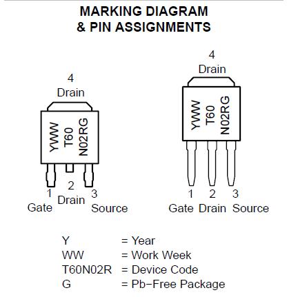
- Each MOSFET will be soldered to the board by 3 seperate pins, the gate, drain, and source....
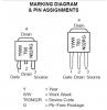
- You need to arm the MOSFET in order to be able to test it right. Hold the negative probe (-) to the center (drain) pin. Now hold the positive probe (+) to the left (gate) pin. You should get no signal, or an "open link" might be displayed on some digital multimeters. If all went well, the internal capacitance of the MOSFET's gate has now been charged by the multimeter and is ready for testing.
- Now you can test it's ability to pass power. Holding the negative probe (-) on the center pin (drain), move the positive probe (+) to the right pin (source). You should get a very low reading, or an indication of a closed circuit by the multimeter beeping.
- Next test whether or not the MOSFET still retains the ability to switch off power. This will tell you the cut-off voltage, which is the highest voltage value that can be put on the gate without it passing a current. Discharge the gate through your finger by touching the source and gate at the same time (its okay if you touch drain also). Holding the negative probe (-) on the center pin (drain) touch the positive probe (+) to the left pin (gate). The multimeter should now show a high reading, indicating the MOSFET is now non-conducting.
- How to tell something is broken...
Usually when a MOSFET short circuits, it shoots the voltage back through the gate into the circuitry, possibly frying other components in the area, including any other MOSFETS that might be connected in parallel with the one that blew.
The following scenarios will indicate that you have a blown/defective MOSFET...
- If you get a singal of continuity by displaying a low number, or the multimeter beeping when you went to arm the MOSFET by touching the negative probe (-) to the center (drain) pin and the positive probe (+) to the left (gate) pin.
- If the multimeter indicates an open circuit warning, which is a high reading on the display when testing the MOSFET ability to pass power.
- If you get an indication of either an open or closed circuit (beep) when trying to test the ability to switch off power.
- If you get a continuity (low number) reading between the source and either the drain or gate pins.
About soldering the MOSFET back on
- First add a bit of solder on the motherboard where the MOSFET will be soldered to. Add just enough rosin flux to make the MOSFET stick in place where it needs to be soldered. Hold it in place with a probe tool and solder each leg back on, holding the iron in place until the solder flowed completely. You will need a pretty good soldering iron to get it hot enough. Let it all cool, then put the 360 back together and test it out. 260C for 10 seconds is the absolute max temp tolerance for the MOSFET during soldering.
Another way to get the replacements back on is to first lay down a dab of solder paste to each of the 3 pads to be soldered to, then preheat the board a bit with a heatgun, then use a hot air rework pencil to do non-contact soldering. Do not try using the paste with a solering iron, or else it can roll up and get under the chip and cause a short.
Source: XBOX-EXPERTS
-
1
-
-
This is incredible, maybe in a few months all the people will be modding their xbox ones. How do you think the hack will be like? glitching or like JTAG?
-
Hello i've installed Forza 4, (both disks patched with ABGX360) I installed the first disc as a .GOD and the second on extracted and putted on the HDD. The problem is that i get Corrupt disc error when playing... but it gives the error at any moment... sometimes you play for 2 hours and no error, then maybe you play for 10 minutes and the error is giving, any advice? thanks


Forza 4
in Games
Posted
You need to put DISC 2 extracted content on HDD/0000000.../GAMEID/
Like any other DLC or game. Good luck