

GoJohnny
-
Content Count
96 -
Joined
-
Last visited
Posts posted by GoJohnny
-
-
Okay, thanks again Swizzy, found it on the Dutch version of Conrad. I'll go look for it at my local electrostore (that's where i bought the other ones as well).
Hope this works, i will defenitly try this, but if it doesn't work, maybe a stupid question, but why does the console boot when i place my thumb on the points of the RF board? Isn't there some way of connecting some of those points to make it boot? ( Sorry, probably a verry noob question, but i just had to ask)
-
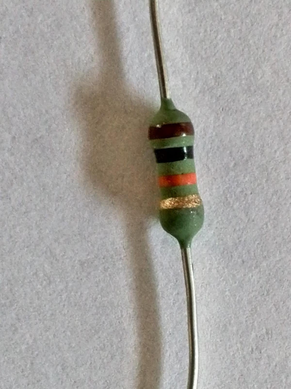
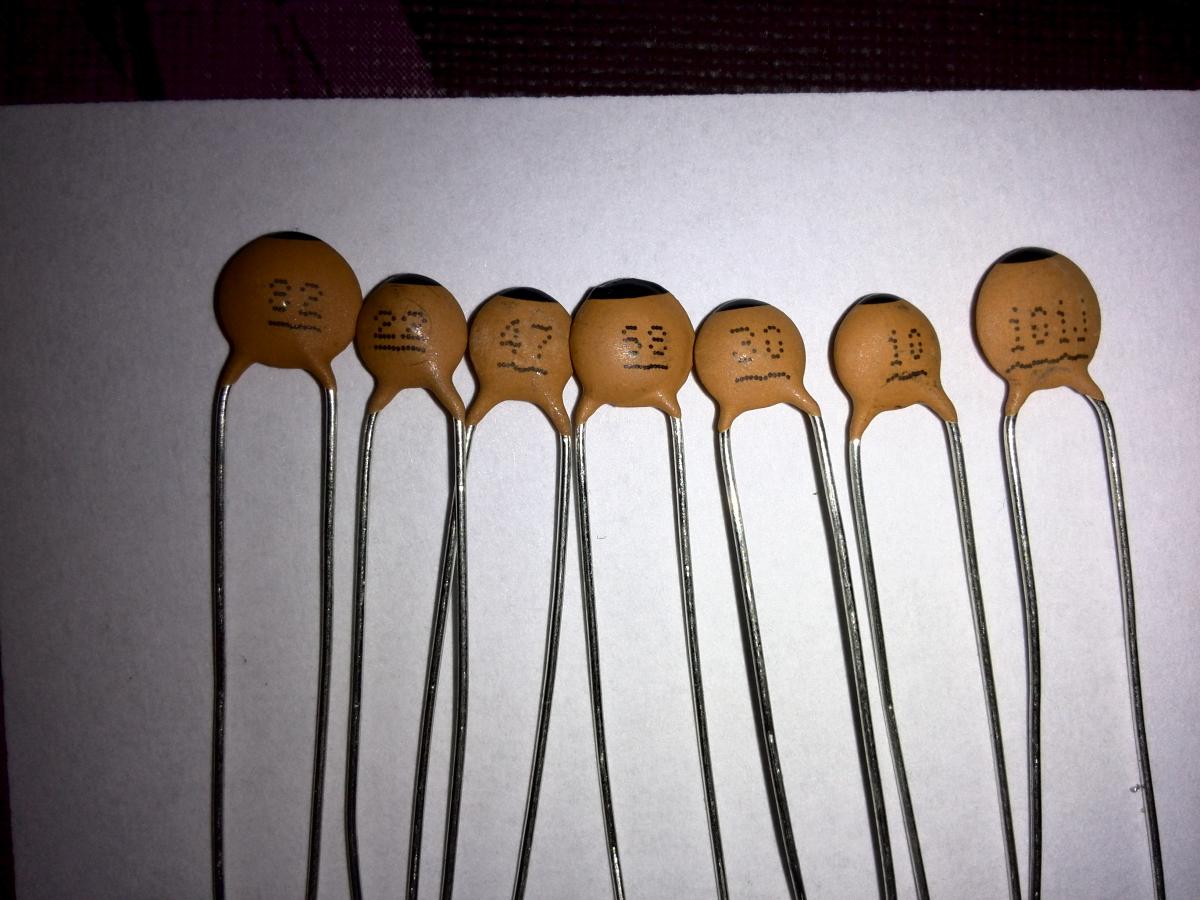
I used a 10K Ohm resistor, like the one shown in the attached picture. Should i use one like that to replace it (i bought a few), or better use another kind of resistor?

-
Hi Swizzy,
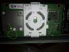
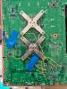
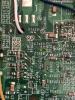
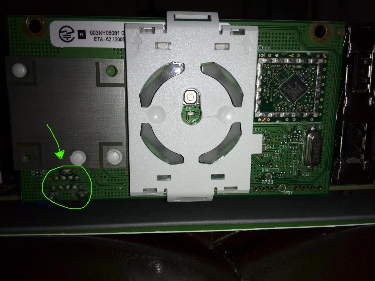
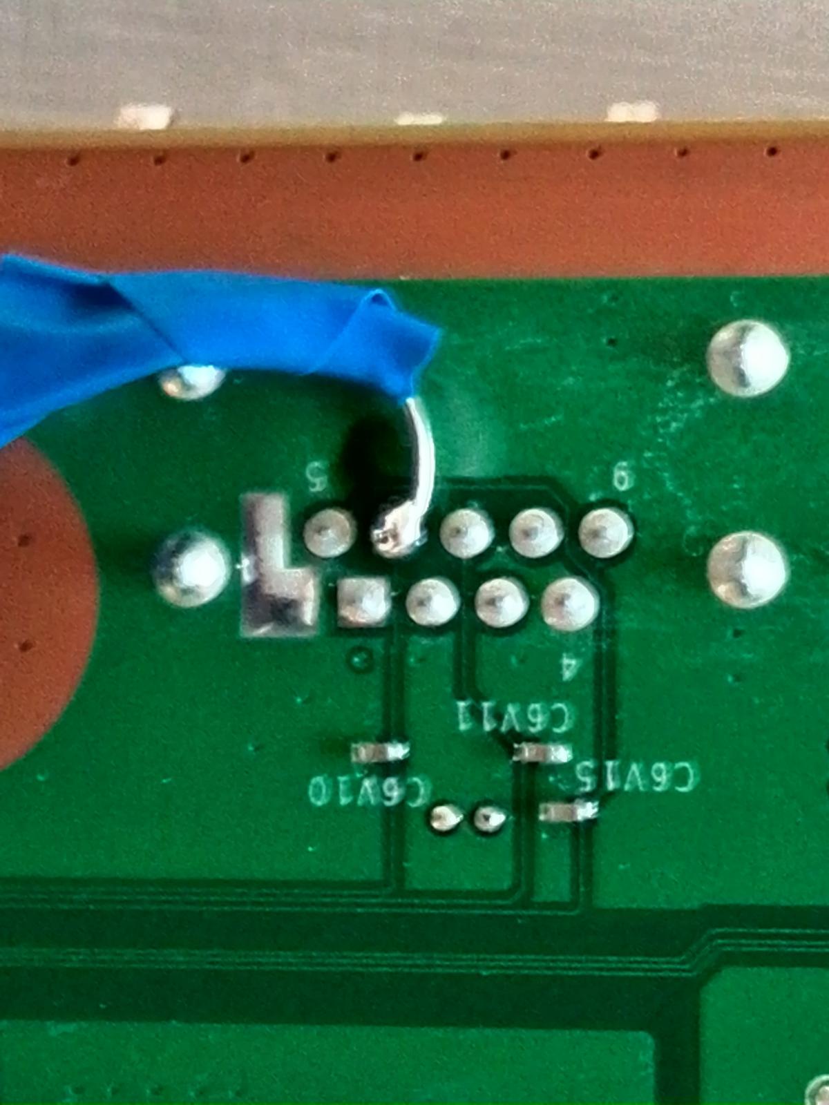
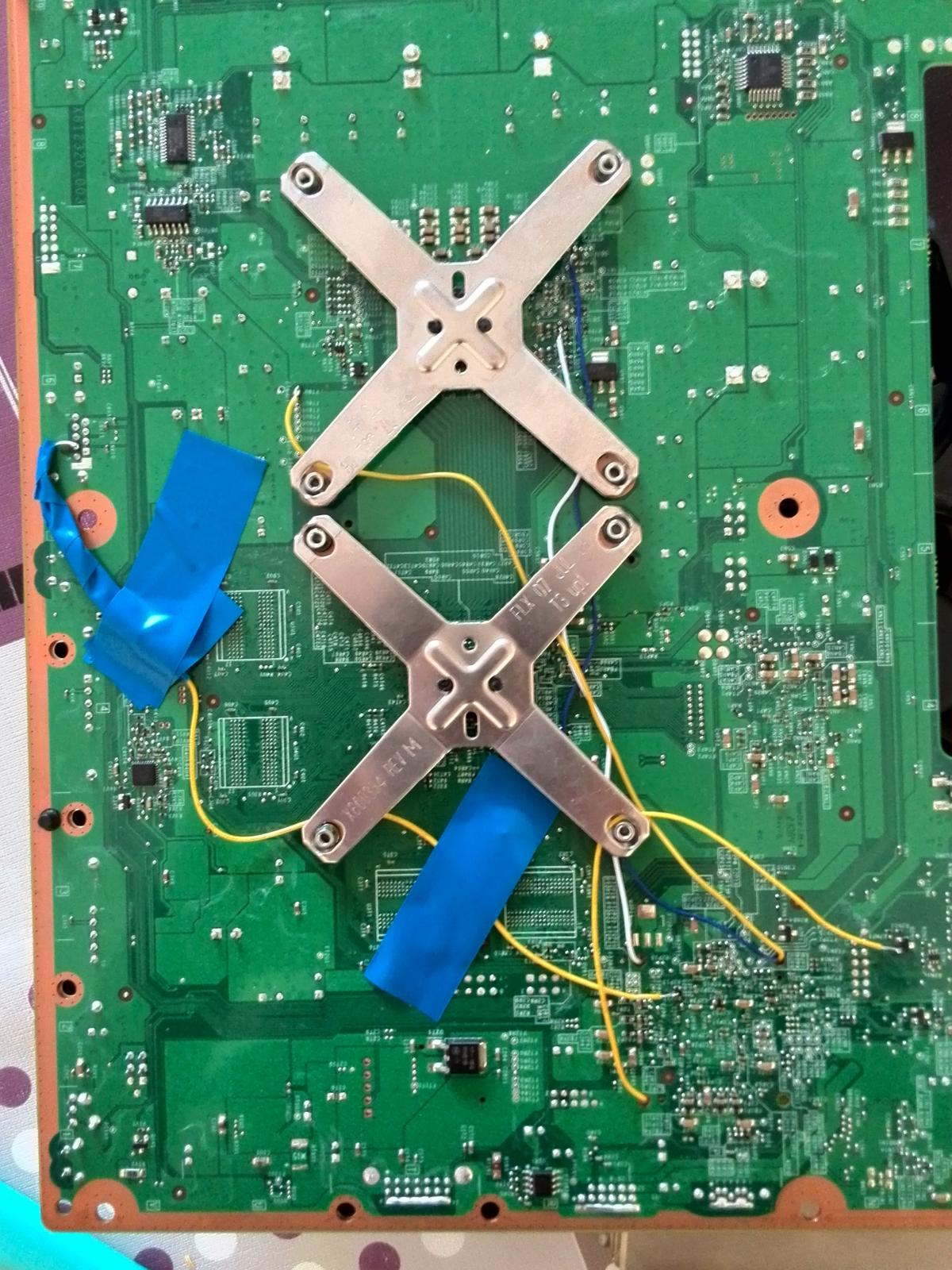
I just found out about something. I thought; maybe the RF board is not connecting to the console like it should be, so i removed the motherboard from the case and pressed the RF board to the console while pushing the start button. And then it immediately booted. But in a later attempt it didn't. So what i found out was that the console only boots when i press my thumb to the place on the RF board i outlined on the attached picture.
Do you know what this means, and what i can do now?
-
On previous pictures you don't see this, but i used a resistor like this (see pic). Could this have anything to do with it? It's a 10K Ohm resistor.
Should i trie connecting other resistors, or could there still be something else that is wrong?
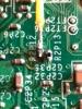
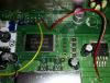
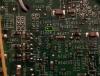
I'll also attach a picture of the top of the board, maybe something is wrong with that?
Hope you can help , getting a bit nuts.

-
I really hoped this would do it, but unfortunatly it still doesn't start with the RF board Connected.
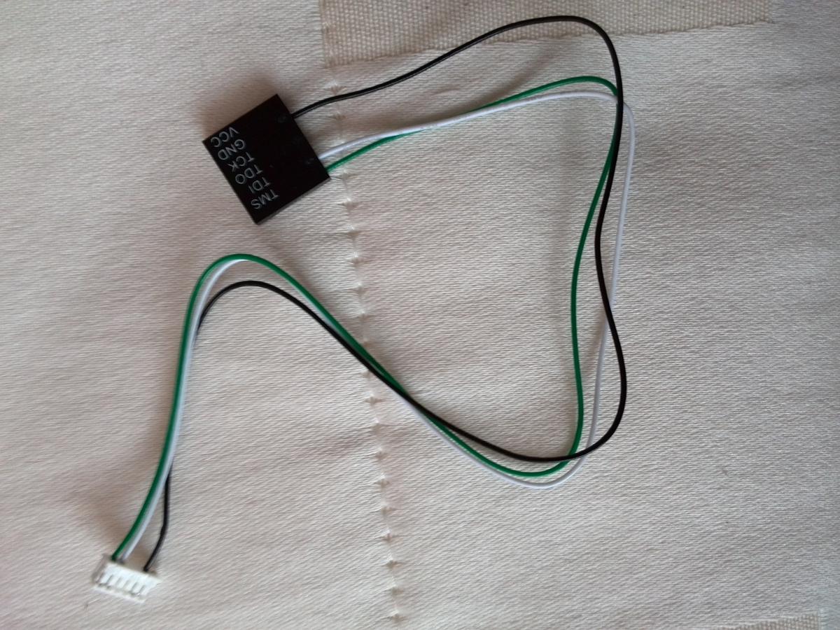
I tried using the start button on the RF board, and i also tried to start using a controller, but te controller doesn't seem to find the RF board.
Only when i remove the RF board, the console starts immediately, and when i then replace the RF board, the controller also finds the RF board.

-
Verry clear diagram, i finally understand, haha. Thanks a lot for all the work you put in to this. I'll try this first thing monday morning. I'll let you know how it worked out.
-
 1
1
-
-
Oke, sorry about that.... Thanks, that would be great.
-
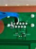
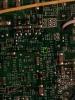
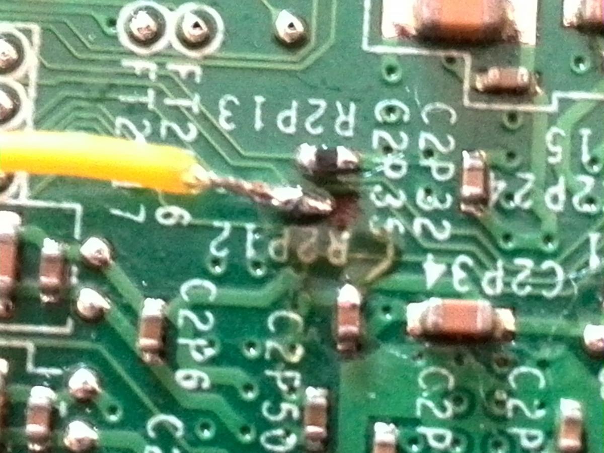
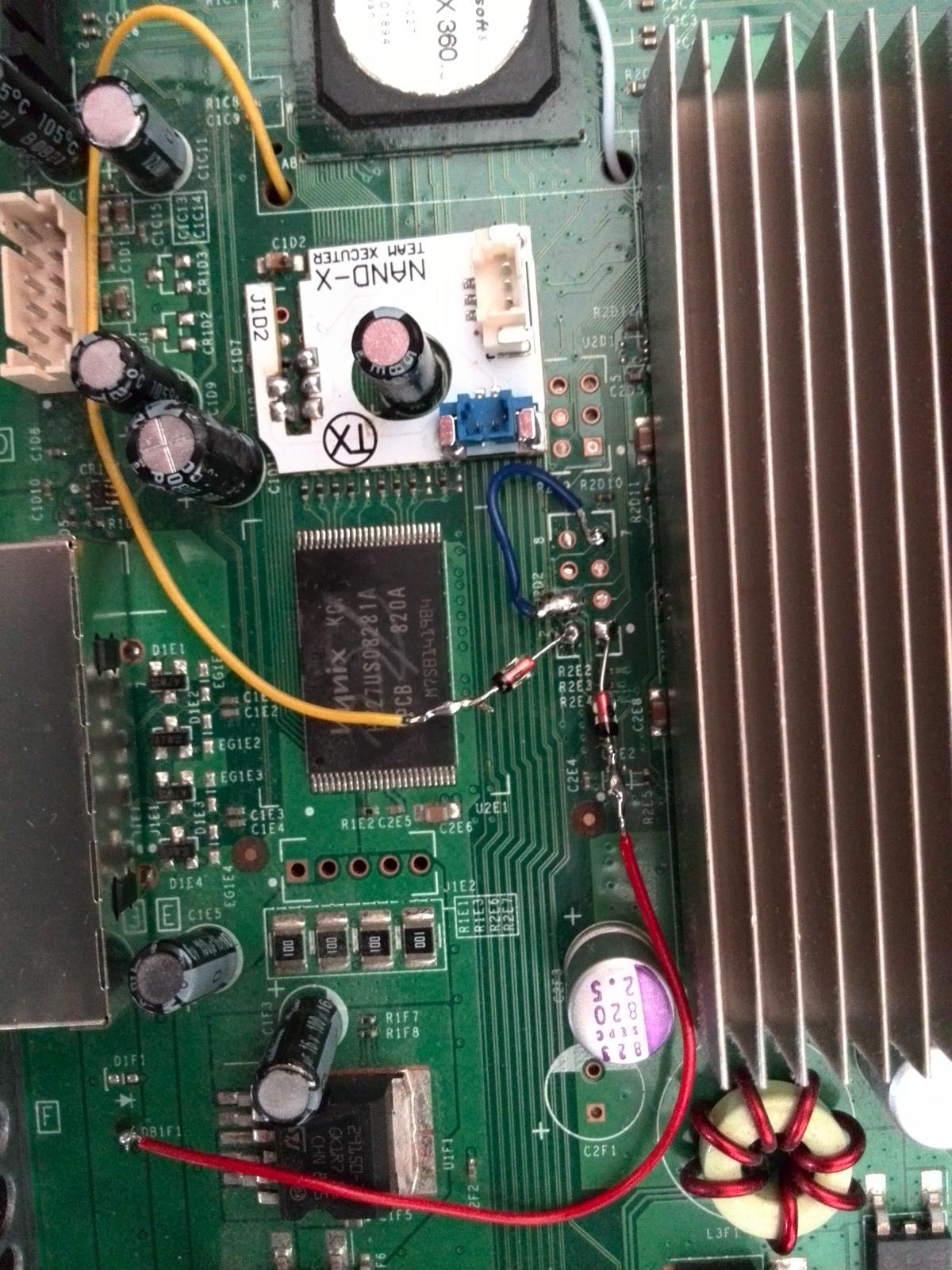
Sorry to keep on asking, but if i am not mistaking i have already Connected that point of the yellow cable (according to the other diagram) to the other side of the board. (see pics)
-
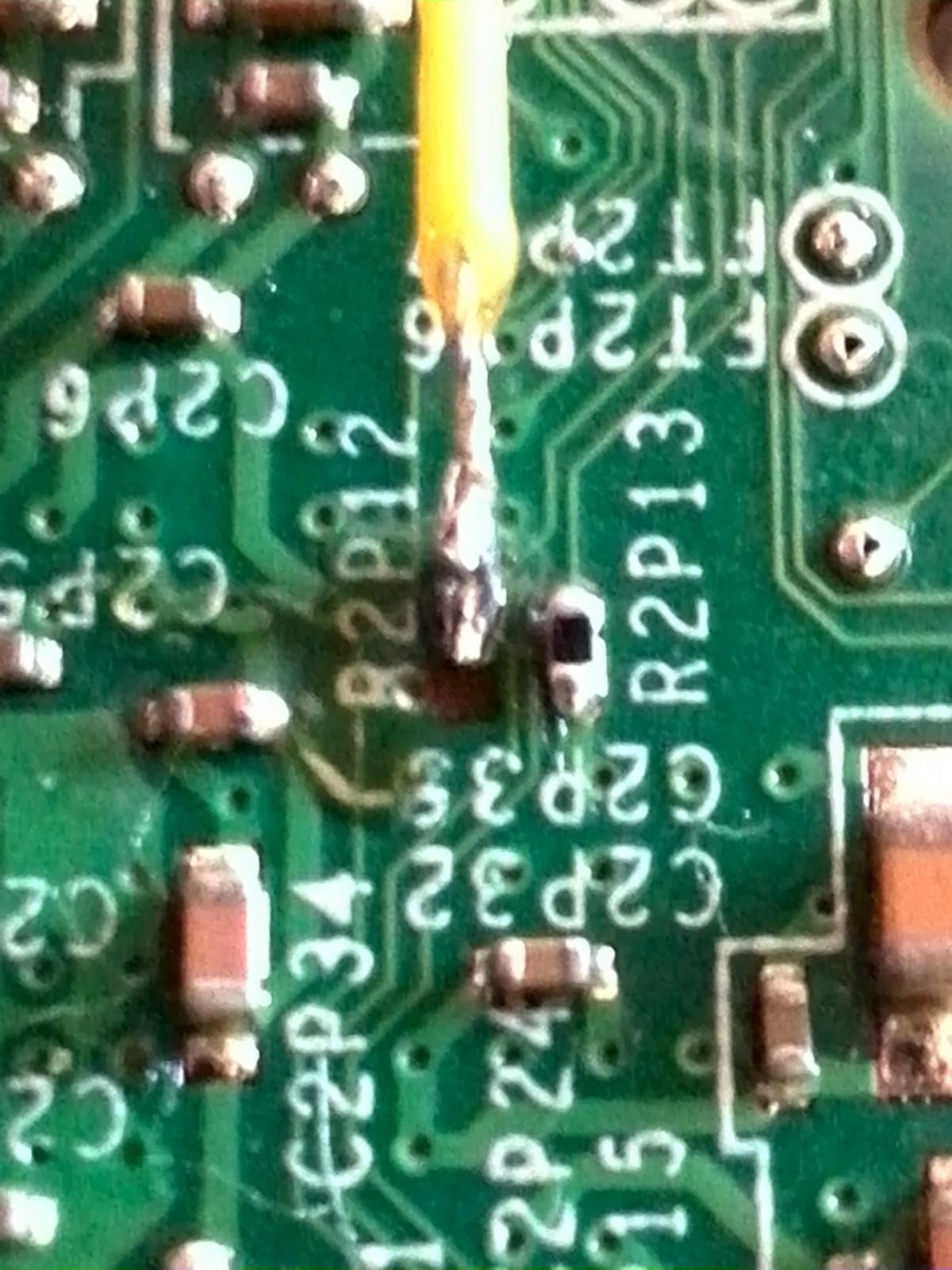
So, when i understand you correctly, i have to solder a resistor to the remaining point of the resistor that is gone, and then wire it to Q2N1?
If that is correct, according to the diagram i used before, i have already soldered a wire coming from the other side of the board, to that point. Does it have to stay there?
-
Okay, but what to do right now? Do i have to scrape the trace on either side of the resistor, solder wire to both sides and then connect it with a 10K Ohm resistor? Or do i have to make some other connections?
-
Hi Swizzy, were you able to map the traces already, or did'n't you have the time to do it yet?
Like i said, no rush of course, just hope you remember me.
Got myself a pair of magnifying glasses right now, hope that will help to do the job.
-
Thanks for the advice gavin_darkglider, but i really can't afford to send it to the UK, and pay a lot of money to get it fixed.
Okay, thank you Swizzy, no rush, i'm glad you're willing to help.
-
Okay, that would be great.
Don't know if it helps, but i made some more pictures.

-
You're right abouth it being difficult to do (really tiny stuff), and so i tried to find someone to do it for me, but unfortunatly without succes. No pro was able or willing to help me (most of them not doing R-Jtag).
So i read a lot more abouth it on the internet and bought some 10K Ohm resistors and even managed to solder it to the points where the resistor was. But when i tried to bend it a little ( to make it fit the case) it came of the board again, and took one of the points with it.
Now i've been searching the net for a fix, but all i read abouth it, is that i should scrape of the trace and make a connection with a resistor, only thing is, i can not find any diagram of how to exactly connect things.
I just hope you can help me out on this one more time? I would be verry thankfull, because the way it is right now, the console is useless.
-
Thanks for the advice, like i said before, this is all new to me. Unfortunatly i don't have someone who could help me out with this, so i guess i'll just give it a trie.
As i look at the picture in my previous post, it looks like there are still two points left on the board that i can solder to, so i think i can manage that. If you could please tell me what i exactly need to order, and if it is okay to solder to that points, or if i have to solder to the trace as well. I'll just take my time and be carefull.
-
can i use one of the resistors that came with the CR4XL? (picture) or do i have to order one at Conrad? If so, do i just have to look for a 10K Ohm resistor, or do i need more specifications?
And can the resistor just be soldered to where it was sitting?

-
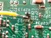
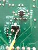
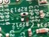
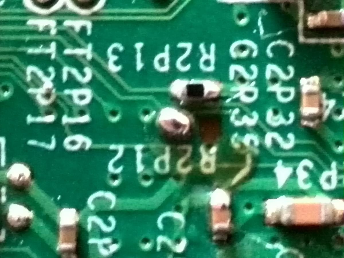
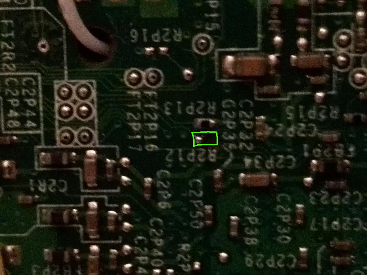
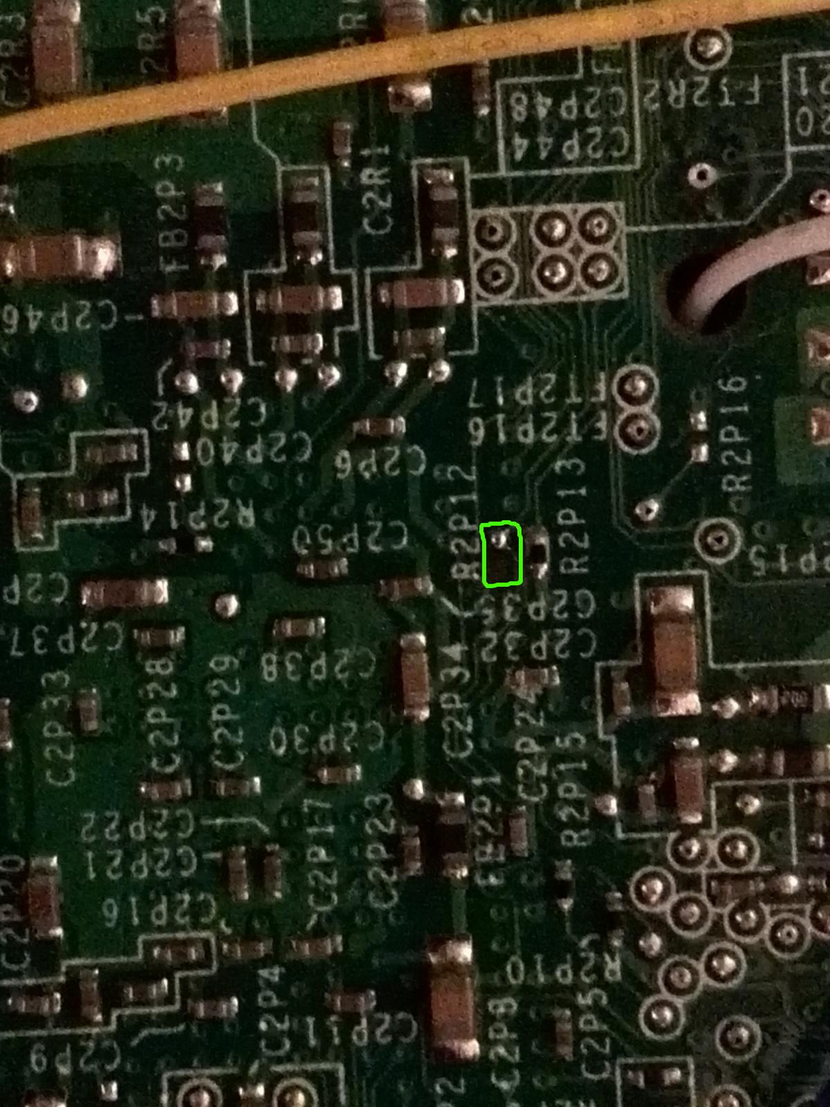
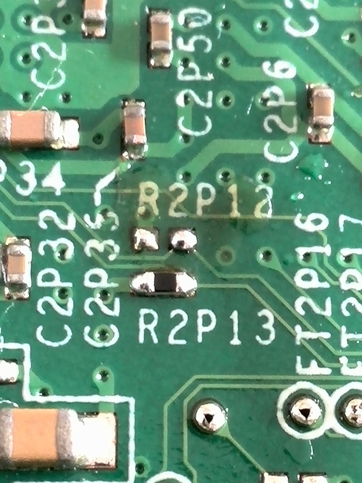
I tried to solder it, but i am afraid it is gone right now (see picture). Maybe it was loose indeed. What to do now????
I assume i have to replace the R2P12 resistor, but what kind of resistor do i need (all i read abouth it, is that is a 10 K Ohm resistor?), and can i just solder it to the motherboard as of where it was?

-
So f i understand you correctly, you don't mean to put the QSB back, but just put some solder on that spot you mentioned?
-
would it be an option to connect the yellow wire to the RF board in stead of to the Q2N1, like they do on the diagram?
-
What do you mean, i removed that QSB you link to?
-
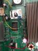
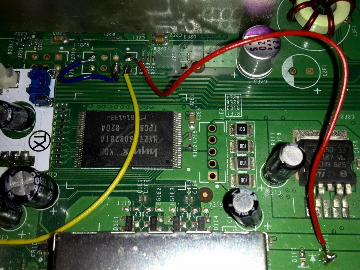
I have now added the two diodes (see pictures), but still the same problem. The Xbox only boots after removing the RF board. Maybe i did something wrong again?
-
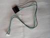
Forgot to ask Swizzy, for the last connection i made, i used wires from this (see picture). Is that allright, our should i use some other wires
-
thanks again suprashake, same to you.
-
Oh, oke, thanks for the pictures, on the picture of the diagram you linked to me, it looked like the red wire was Connected to the top of the board, and so i did. But now i see on your pics that it goes to the bottom side?
So, now i go get myself some diodes, and get back to you when everything is ready.
Oh, and yes, i do come from the beautiful Netherlands.
Haha Suprashake, thanks for the support. It was actually more my way of appologizing, but thanks anyway.
-
1
-


R-Jtag Xell doesn't start
in Other topics
Posted
Ah, okay, thanks a lot for explaining, that totaly fulfilled my curiosity.